Docs
Micro-controllers, wireless transmission and database

NEMA 17 Motor & L298N with Blue Pill using STM32CubeIDE
Prerequisites
This project assumes you have already installed STM32CubeIDE. You need to have previously done a basic blink sketch with blue-pill using STM32CubeIDE. I have made a complete video from installing STM32CubeIDE to LED blink program. You can watch it by clicking this link. https://www.youtube.com/watch?v=kXg467nVd_A
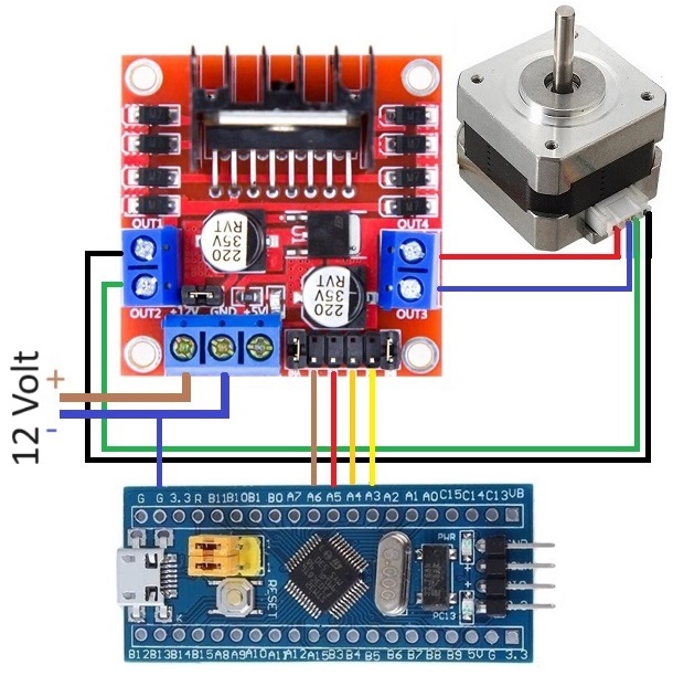
Wiring Diagram
STM32CubeIDE Settings
Click RCC → High Speed Clock (HSE) to Crystal/Ceramic Resonator
Click Clock Configuration tab → HCLK (MHz) to 72
Click Pinout and Configuration tab
Click Timer → Click TIM2 →
Clock Source set to Internal Clock
Configuration → Parameter Settings →
Prescaler set to 71
Set PA3, PA4, PA5 and PA6 GPIO_Output
Additional code on top of STM32CubeIDE generated code
/* USER CODE BEGIN 0 */
#define IN1_PIN GPIO_PIN_6
#define IN1_PORT GPIOA
#define IN2_PIN GPIO_PIN_5
#define IN2_PORT GPIOA
#define IN3_PIN GPIO_PIN_4
#define IN3_PORT GPIOA
#define IN4_PIN GPIO_PIN_3
#define IN4_PORT GPIOA
int stepNumber;          // which step the motor is on

void motorDelay(uint32_t delay)
{
    if (delay < 60000)
    {
        __HAL_TIM_SET_COUNTER(&htim2, 0);
        while (__HAL_TIM_GET_COUNTER(&htim2) < delay);
    }
    else
    {
        HAL_Delay(delay/1000);
    }
}

void motorOn()
{
    // Find out which step the motor is on
    switch (stepNumber)
    {
      case 1:
          HAL_GPIO_WritePin(IN1_PORT, IN1_PIN, GPIO_PIN_SET);   // IN1
          HAL_GPIO_WritePin(IN2_PORT, IN2_PIN, GPIO_PIN_RESET); // IN2
          HAL_GPIO_WritePin(IN3_PORT, IN3_PIN, GPIO_PIN_RESET); // IN3
          HAL_GPIO_WritePin(IN4_PORT, IN4_PIN, GPIO_PIN_SET);   // IN4
          HAL_Delay(5);
        break;
      case 2:
          HAL_GPIO_WritePin(IN1_PORT, IN1_PIN, GPIO_PIN_SET);   // IN1
          HAL_GPIO_WritePin(IN2_PORT, IN2_PIN, GPIO_PIN_RESET); // IN2
          HAL_GPIO_WritePin(IN3_PORT, IN3_PIN, GPIO_PIN_SET);   // IN3
          HAL_GPIO_WritePin(IN4_PORT, IN4_PIN, GPIO_PIN_RESET); // IN4
          HAL_Delay(5);
        break;
      case 3:
          HAL_GPIO_WritePin(IN1_PORT, IN1_PIN, GPIO_PIN_RESET); // IN1
          HAL_GPIO_WritePin(IN2_PORT, IN2_PIN, GPIO_PIN_SET);   // IN2
          HAL_GPIO_WritePin(IN3_PORT, IN3_PIN, GPIO_PIN_SET);   // IN3
          HAL_GPIO_WritePin(IN4_PORT, IN4_PIN, GPIO_PIN_RESET); // IN4
          HAL_Delay(5);
        break;
      case 4:
          HAL_GPIO_WritePin(IN1_PORT, IN1_PIN, GPIO_PIN_RESET); // IN1
          HAL_GPIO_WritePin(IN2_PORT, IN2_PIN, GPIO_PIN_SET);   // IN2
          HAL_GPIO_WritePin(IN3_PORT, IN3_PIN, GPIO_PIN_RESET); // IN3
          HAL_GPIO_WritePin(IN4_PORT, IN4_PIN, GPIO_PIN_SET);   // IN4
          HAL_Delay(5);
        break;
      default:
        break;
    }
}
void motorOff()
{
    // Switch off the idle current to the motor
    // Otherwise L298N module will heat up
    HAL_GPIO_WritePin(IN1_PORT, IN1_PIN, GPIO_PIN_RESET); // IN1
    HAL_GPIO_WritePin(IN2_PORT, IN2_PIN, GPIO_PIN_RESET); // IN2
    HAL_GPIO_WritePin(IN3_PORT, IN3_PIN, GPIO_PIN_RESET); // IN3
    HAL_GPIO_WritePin(IN4_PORT, IN4_PIN, GPIO_PIN_RESET); // IN4
}
void stepCV (int steps, float speed) // CV - Clockwise
{
  uint32_t delay = 60*1000*1000/200/speed;
  for(int x=0; x<steps; x=x+1)
  {
    // Step to the next step
    switch (stepNumber)
    {
      case 1:
        HAL_GPIO_WritePin(IN1_PORT, IN1_PIN, GPIO_PIN_SET);   // IN1
        HAL_GPIO_WritePin(IN2_PORT, IN2_PIN, GPIO_PIN_RESET); // IN2
        HAL_GPIO_WritePin(IN3_PORT, IN3_PIN, GPIO_PIN_SET);   // IN3
        HAL_GPIO_WritePin(IN4_PORT, IN4_PIN, GPIO_PIN_RESET); // IN4
        motorDelay(delay);
        stepNumber = 2;
        break;
      case 2:
        HAL_GPIO_WritePin(IN1_PORT, IN1_PIN, GPIO_PIN_RESET); // IN1
        HAL_GPIO_WritePin(IN2_PORT, IN2_PIN, GPIO_PIN_SET);   // IN2
        HAL_GPIO_WritePin(IN3_PORT, IN3_PIN, GPIO_PIN_SET);   // IN3
        HAL_GPIO_WritePin(IN4_PORT, IN4_PIN, GPIO_PIN_RESET); // IN4
        motorDelay(delay);
        stepNumber = 3;
        break;
      case 3:

        HAL_GPIO_WritePin(IN1_PORT, IN1_PIN, GPIO_PIN_RESET); // IN1
        HAL_GPIO_WritePin(IN2_PORT, IN2_PIN, GPIO_PIN_SET);   // IN2
        HAL_GPIO_WritePin(IN3_PORT, IN3_PIN, GPIO_PIN_RESET); // IN3
        motorDelay(delay);
        stepNumber = 4;
        break;
      case 4:
        HAL_GPIO_WritePin(IN1_PORT, IN1_PIN, GPIO_PIN_SET);   // IN1
        HAL_GPIO_WritePin(IN2_PORT, IN2_PIN, GPIO_PIN_RESET); // IN2
        HAL_GPIO_WritePin(IN3_PORT, IN3_PIN, GPIO_PIN_RESET); // IN3
        HAL_GPIO_WritePin(IN4_PORT, IN4_PIN, GPIO_PIN_SET);   // IN4
        motorDelay(delay);
        stepNumber = 1;
        break;
      default:
        break;
    }
  }
}
void stepCCV (int steps, float speed) // CCV - Counter Clockwise
{
  uint32_t delay = 60*1000*1000/200/speed;
  for(int x=0; x<steps; x=x+1)
  {
    // Step to the previous step
    switch (stepNumber)
    {
      case 1:
        HAL_GPIO_WritePin(IN1_PORT, IN1_PIN, GPIO_PIN_RESET); // IN1
        HAL_GPIO_WritePin(IN2_PORT, IN2_PIN, GPIO_PIN_SET);   // IN2
        HAL_GPIO_WritePin(IN3_PORT, IN3_PIN, GPIO_PIN_RESET); // IN3
        HAL_GPIO_WritePin(IN4_PORT, IN4_PIN, GPIO_PIN_SET);   // IN4
        motorDelay(delay);
        stepNumber = 4;
        break;
      case 2:
        HAL_GPIO_WritePin(IN1_PORT, IN1_PIN, GPIO_PIN_SET);   // IN1
        HAL_GPIO_WritePin(IN2_PORT, IN2_PIN, GPIO_PIN_RESET); // IN2
        HAL_GPIO_WritePin(IN3_PORT, IN3_PIN, GPIO_PIN_RESET); // IN3
        HAL_GPIO_WritePin(IN4_PORT, IN4_PIN, GPIO_PIN_SET);   // IN4
        motorDelay(delay);
        stepNumber = 1;
        break;
      case 3:
        HAL_GPIO_WritePin(IN1_PORT, IN1_PIN, GPIO_PIN_SET);   // IN1
        HAL_GPIO_WritePin(IN2_PORT, IN2_PIN, GPIO_PIN_RESET); // IN2
        HAL_GPIO_WritePin(IN3_PORT, IN3_PIN, GPIO_PIN_SET);   // IN3
        HAL_GPIO_WritePin(IN4_PORT, IN4_PIN, GPIO_PIN_RESET); // IN4
        motorDelay(delay);
        stepNumber = 2;
        break;
      case 4:
        HAL_GPIO_WritePin(IN1_PORT, IN1_PIN, GPIO_PIN_RESET); // IN1
        HAL_GPIO_WritePin(IN2_PORT, IN2_PIN, GPIO_PIN_SET);   // IN2
        HAL_GPIO_WritePin(IN3_PORT, IN3_PIN, GPIO_PIN_SET);   // IN3
        HAL_GPIO_WritePin(IN4_PORT, IN4_PIN, GPIO_PIN_RESET); // IN4
        motorDelay(delay);
        stepNumber = 3;
        break;
      default:
        break;
    }
  }
}
/* USER CODE END 0 */

  /* USER CODE BEGIN 2 */
  HAL_TIM_Base_Start(&htim2);
  stepNumber = 1;
  /* USER CODE END 2 */

  /* Infinite loop */
  /* USER CODE BEGIN WHILE */
  while (1)
  {
    motorOn();
    stepCV(200,150.0f); // Clockwise 200 steps 150 RPM
    motorOff();
    HAL_Delay(2000);

    motorOn();
    stepCCV(100,150.0f); // Counter Clockwise 100 steps 150 RPM
    motorOff();
    HAL_Delay(2000);

    motorOn();
    stepCV(7,0.5f); // Clockwise 7 steps 1/2 RPM
    motorOff();
    HAL_Delay(2000);

    motorOn();
    stepCCV(9,0.5f); // Counter Clockwise 9 steps 1/2 RPM
    motorOff();
    HAL_Delay(2000);

    motorOn();
    stepCV(1500,30.0f); // Clockwise 1500 steps 30 RPM
    motorOff();
    HAL_Delay(2000);
    /* USER CODE END WHILE */

    /* USER CODE BEGIN 3 */
  }
  /* USER CODE END 3 */