Docs
Micro-controllers, wireless transmission and database

74HC595 7-Segment Display with Blue Pill using STM32CubeIDE
Prerequisites
This project assumes you have already installed STM32CubeIDE. You need to have previously done a basic blink sketch with blue-pill using STM32CubeIDE. I have made a complete video from installing STM32CubeIDE to LED blink program. You can watch it by clicking this link. https://www.youtube.com/watch?v=kXg467nVd_A
Wiring Diagram
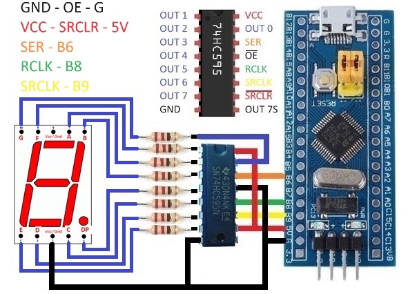
STM32CubeIDE Settings
Set PB6, PB8 and PB9 to GPIO_Output
Additional code on top of STM32CubeIDE generated code
/* USER CODE BEGIN 0 */
#define SER_PIN GPIO_PIN_6
#define SER_PORT GPIOB
#define RCLK_PIN GPIO_PIN_8
#define RCLK_PORT GPIOB
#define SRCLK_PIN GPIO_PIN_9
#define SRCLK_PORT GPIOB

uint8_t number[10] =   {0b01110111,
                        0b00010100,
                        0b10110011,
                        0b10110110,
                        0b11010100,
                        0b11100110,
                        0b11100111,
                        0b00110100,
                        0b11110111,
                        0b11110110};

void HC595write(uint8_t val)
{
    for(int i=0; i<8; i++)
    {
        if(number[val] & (1<<i))
        {
            HAL_GPIO_WritePin(SER_PORT, SER_PIN, GPIO_PIN_SET);
        }
        else
        {
            HAL_GPIO_WritePin(SER_PORT, SER_PIN, GPIO_PIN_RESET);
        }
        HAL_GPIO_WritePin(SRCLK_PORT, SRCLK_PIN, GPIO_PIN_SET);
        HAL_GPIO_WritePin(SRCLK_PORT, SRCLK_PIN, GPIO_PIN_RESET);
    }
    HAL_GPIO_WritePin(RCLK_PORT, RCLK_PIN, GPIO_PIN_SET);
    HAL_GPIO_WritePin(RCLK_PORT, RCLK_PIN, GPIO_PIN_RESET);
}
/* USER CODE END 0 */

  /* USER CODE BEGIN WHILE */
  while (1)
  {
    for(int x=0; x<10; x++)
    {
      HC595write(x);
      HAL_Delay(1000);
    }
    /* USER CODE END WHILE */