Docs
Micro-controllers, wireless transmission and database

Internal RTC/Alarm with Blue Pill using STM32CubeIDE
Prerequisites
This project assumes you have already installed STM32CubeIDE. You need to have previously done a basic blink sketch with blue-pill using STM32CubeIDE. I have made a complete video from installing STM32CubeIDE to LED blink program. You can watch it by clicking this link. https://www.youtube.com/watch?v=kXg467nVd_A
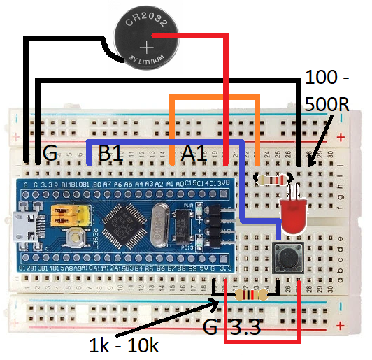
Wiring Diagram

STM32CubeIDE Settings
Click RCC → High Speed Clock (HSE) to Crystal/Ceramic Resonator
Low Speed Clock (LSE) to Crystal/Ceramic Resonator
Click Clock Configuration tab → HCLK (MHz) to 72
Click Pinout and Configuration tab
Click Timer → Click RTC →
Activate Clock Source (Tick)
Activate Calendar (Tick)
RTC OUT → Select RTC Output on Tamper Pin
Configuration → Parameter Settings →
Set Calendar time (Set few mimutes forward as this will be code uploding time
Set Alarm A
Configuration → NVIC Settings →
RTC alarm interrupt through EXTI (Tick)
Set PA1 to GPIO_Output
Set PB1 to GPIO_Input
Additional code on top of STM32CubeIDE generated code
/* USER CODE BEGIN PV */
RTC_TimeTypeDef gTime;
/* USER CODE END PV */

  /* USER CODE BEGIN WHILE */
  while (1)
  {
    if(HAL_GPIO_ReadPin(GPIOB, GPIO_PIN_1) == GPIO_PIN_SET)
    {
      HAL_GPIO_WritePin(GPIOA, GPIO_PIN_1, 0);
    }
    HAL_RTC_GetTime(&hrtc, &gTime, RTC_FORMAT_BIN);
    // to get hours use -- gTime.Hours
    // to get minutes use -- gTime.Minutes
    // to get s econds use -- gTime.Seconds
    HAL_Delay(500);
    /* USER CODE END WHILE */

    /* USER CODE BEGIN 3 */
  }
  /* USER CODE END 3 */

/* USER CODE BEGIN 4 */
void HAL_RTC_AlarmAEventCallback(RTC_HandleTypeDef *hrtc)
{
  HAL_GPIO_WritePin(GPIOA, GPIO_PIN_1,1);
}
/* USER CODE END 4 */