Docs
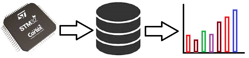
Micro-controllers, wireless transmission and database
Timer interrupt with Blue Pill using STM32CubeIDE
Prerequisites
This project assumes you have already installed STM32CubeIDE. You need to have previously done a basic blink sketch with blue-pill using STM32CubeIDE. I have made a complete video from installing STM32CubeIDE to LED blink program. You can watch it by clicking this link. https://www.youtube.com/watch?v=kXg467nVd_A
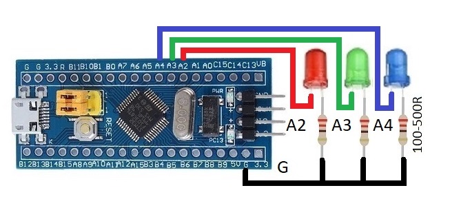
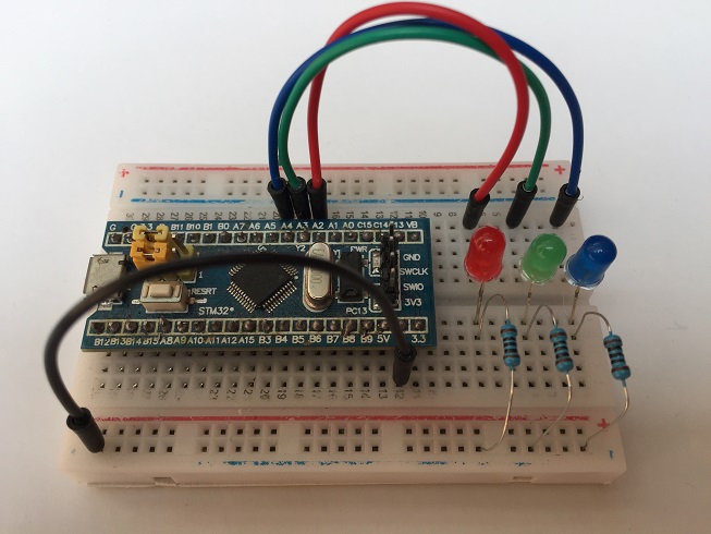
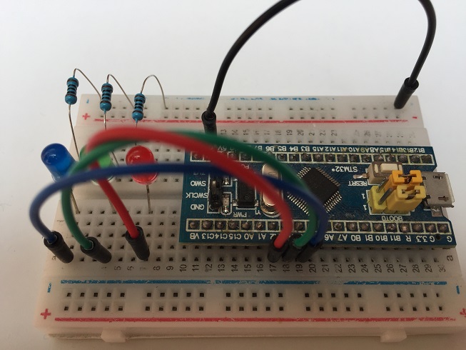
Wiring Diagram
STM32CubeIDE Settings
Click RCC → High Speed Clock (HSE) to Crystal/Ceramic Resonator
Click Clock Configuration tab → HCLK (MHz) to 72
Click Pinout and Configuration tab
Click Timer → Click TIM2 →
Clock Source set to Internal Clock (Select)
Configuration → Parameter Settings →
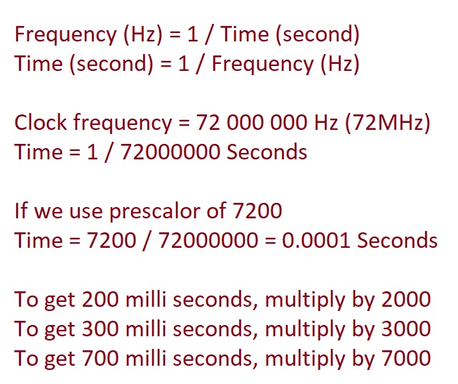
Prescaler set to 7200
Counter Period to 2000
Configuration → NVIC Settings → TIM2 global interrupt (Tick)
Click Timer → Click TIM3 →
Internal Clock (Tick)
Configuration → Parameter Settings →
Prescaler set to 7200
Counter Period to 3000
Configuration → NVIC Settings → TIM3 global interrupt (Tick)
Click Timer → Click TIM4 →
Internal Clock (Tick)
Configuration → Parameter Settings →
Prescaler set to 7200
Counter Period to 7000
Configuration → NVIC Settings → TIM4 global interrupt (Tick)
Set PA2, PA3 and PA4 GPIO_Output
Additional code on top of STM32CubeIDE generated code
  /* USER CODE BEGIN 2 */
  HAL_TIM_Base_Start_IT(&htim2);
  HAL_TIM_Base_Start_IT(&htim3);
  HAL_TIM_Base_Start_IT(&htim4);
  /* USER CODE END 2 */

/* USER CODE BEGIN 4 */
void HAL_TIM_PeriodElapsedCallback(TIM_HandleTypeDef *htim)
{
  if(htim->Instance == TIM2)
  {
    HAL_GPIO_TogglePin(GPIOA, GPIO_PIN_2);
  }
  if(htim->Instance == TIM3)
  {
    HAL_GPIO_TogglePin(GPIOA, GPIO_PIN_3);
  }
  if(htim->Instance == TIM4)
  {
    HAL_GPIO_TogglePin(GPIOA, GPIO_PIN_4);
  }
}
/* USER CODE END 4 */