Docs
Micro-controllers, wireless transmission and database
Rotary Encoder with Blue Pill using STM32CubeIDE
Prerequisites
This project assumes you have already installed STM32CubeIDE. You need to have previously done a basic blink sketch with blue-pill using STM32CubeIDE. I have made a complete video from installing STM32CubeIDE to LED blink program. You can watch it by clicking this link. https://www.youtube.com/watch?v=kXg467nVd_A
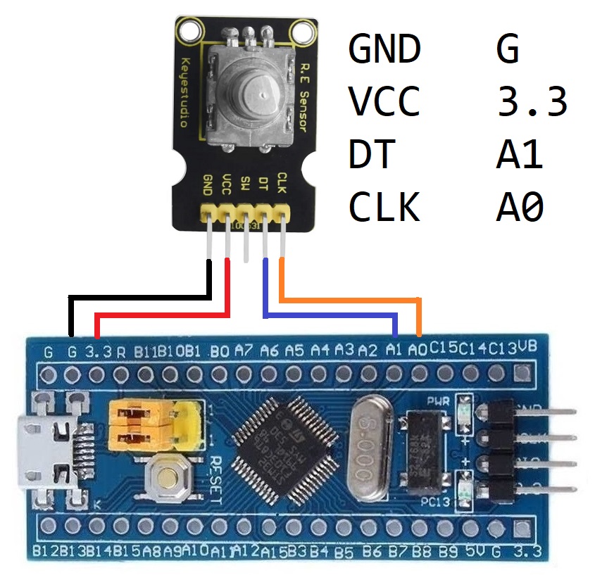
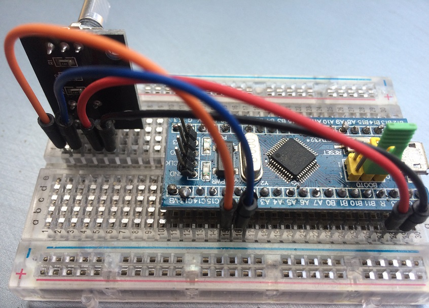
Wiring Diagram
STM32CubeIDE Settings
Click RCC → High Speed Clock (HSE) to Crystal/Ceramic Resonator
Click Clock Configuration tab → HCLK (MHz) to 72
Click Pinout and Configuration tab
Click Timer → Click TIM2 →
Combined Channels set to Encoder Mode
Configuration → Parameter Settings →
Counter Period 65535
Encoder Mode set to Encoder Mode T1 and T2
Set PC13 to GPIO_Output
Additional code on top of STM32CubeIDE generated code (in main.c)
/* USER CODE BEGIN 2 */
HAL_TIM_Encoder_Start(&htim2, TIM_CHANNEL_ALL);
uint32_t counter = 0;
/* USER CODE END 2 */
/* Infinite loop */
/* USER CODE BEGIN WHILE */
while (1)
{
  counter = __HAL_TIM_GET_COUNTER(&htim2);
  if (counter > 60000)
  {
    __HAL_TIM_SET_COUNTER(&htim2,0);
    counter=0;
  }
  if (counter > 100)
  {
    __HAL_TIM_SET_COUNTER(&htim2,100);
    counter=100;
  }
  HAL_GPIO_TogglePin(GPIOC, GPIO_PIN_13);
  HAL_Delay(counter);
  /* USER CODE END WHILE */
  /* USER CODE BEGIN 3 */
}
/* USER CODE END 3 */