Docs
Micro-controllers, wireless transmission and database
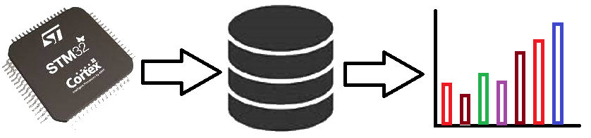
Optocoupler sensor module as RPM meter (Tachometer) with Blue Pill using STM32CubeIDE
Prerequisites
This project assumes you have already installed STM32CubeIDE. You need to have previously done a basic blink sketch with blue-pill using STM32CubeIDE. I have made a complete video from installing STM32CubeIDE to LED blink program. You can watch it by clicking this link. https://www.youtube.com/watch?v=kXg467nVd_A
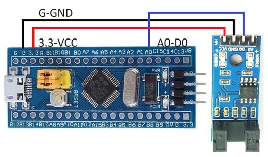
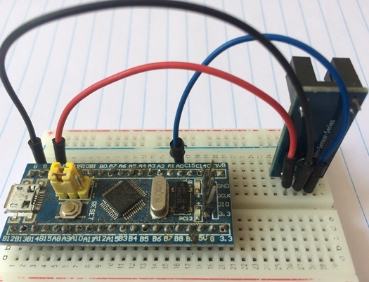
Wiring Diagram
STM32CubeIDE Settings
Click RCC → High Speed Clock (HSE) to Crystal/Ceramic Resonator
Click Clock Configuration tab → HCLK (MHz) to 72
Click Pinout and Configuration tab
Click Timer → Click TIM2 →
Clock source to Internal Clock
Channel 1 set to Input Capture direct Mode
Configuration → NVIC Settings →
TIM2 global interrupt (tick)
Additional code on top of STM32CubeIDE generated code (in main.c)
/* USER CODE BEGIN 0 */
uint32_t counter = 0;
int speed = 0; // Tick per second
int rpm = 0; // Revolutions Per Minute
void HAL_TIM_IC_CaptureCallback(TIM_HandleTypeDef *htim)
{
  counter++;
}
/* USER CODE END 0 */

/* USER CODE BEGIN 2 */
HAL_TIM_Encoder_Start_IT(&htim2, TIM_CHANNEL_1 );
/* USER CODE END 2 */
Additional code on top of STM32CubeIDE generated code (in stm32f1xx_it.c)
/* USER CODE BEGIN 0 */
extern uint32_t counter;
extern int speed;
extern int rpm;
int count = 0;
uint32_t oldcounter = 0;
/* USER CODE END 0 */

/* USER CODE BEGIN SysTick_IRQn 0 */
count++;
if (count == 1000)
{
  speed = counter - oldcounter; // Tick per second
  rpm = speed * 60 / 20; // Revolutions Per Minute
  oldcounter = counter;
  count = 0;
}
/* USER CODE END SysTick_IRQn 0 */